BBG TCG Card Sorter — Assembly Guide
Bearly Board Gaming — Trading Card Game Sorter STL Assembly Guide
Table of Contents
- Printing Orientation Notes
- Base – Outer
- Base – Inner
- Scanner
- Flappers (Repeat x9)
- Cross Braces (Repeat x2)
- Raspberry Pi Mount
- Tray
- Tray Guides
- Final Assembly
- Extras
Printing Orientation Notes
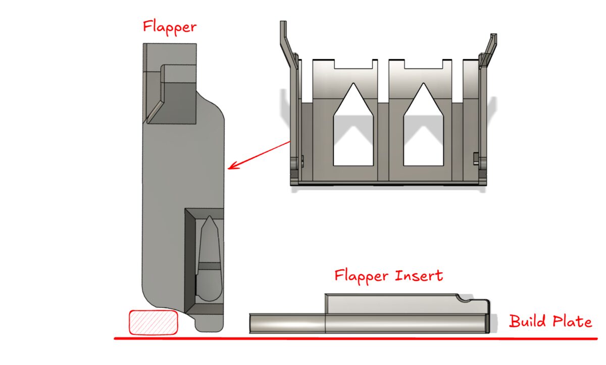
In most cases orient the objects so they use as little supports as possible. In the following cases a less efficient orientation must be used to prevent feeding issues:
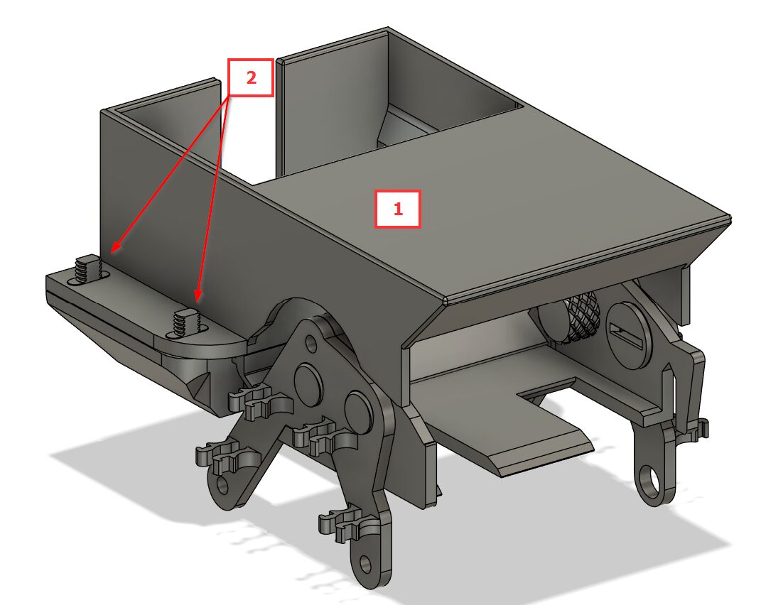
Base
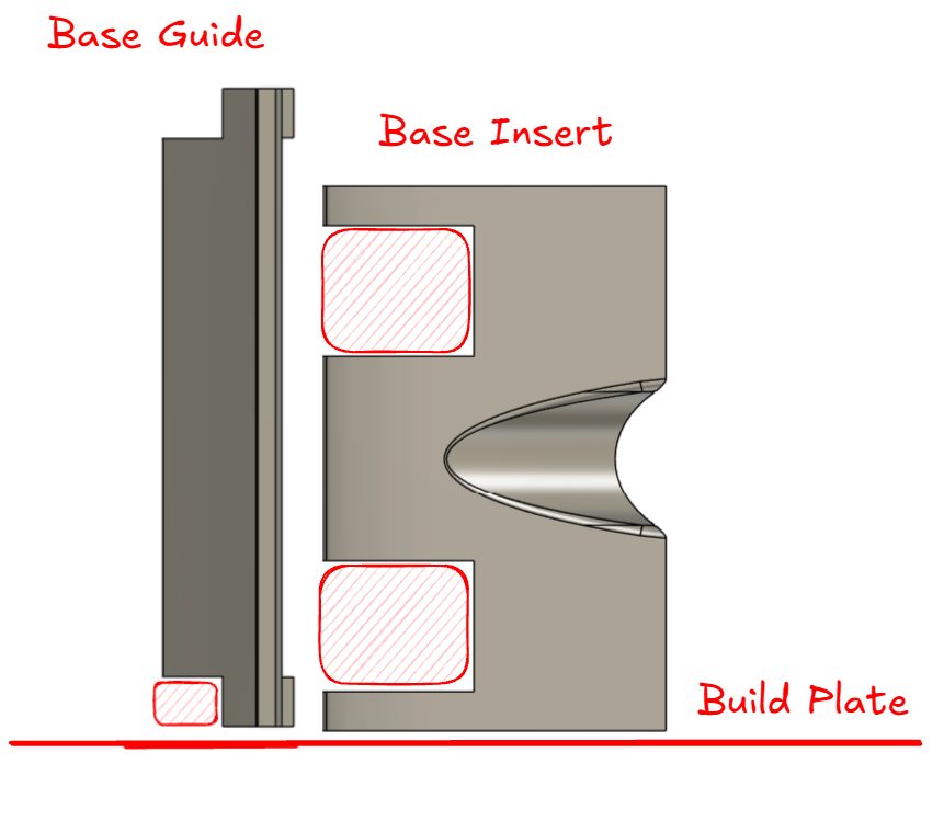
Scanner
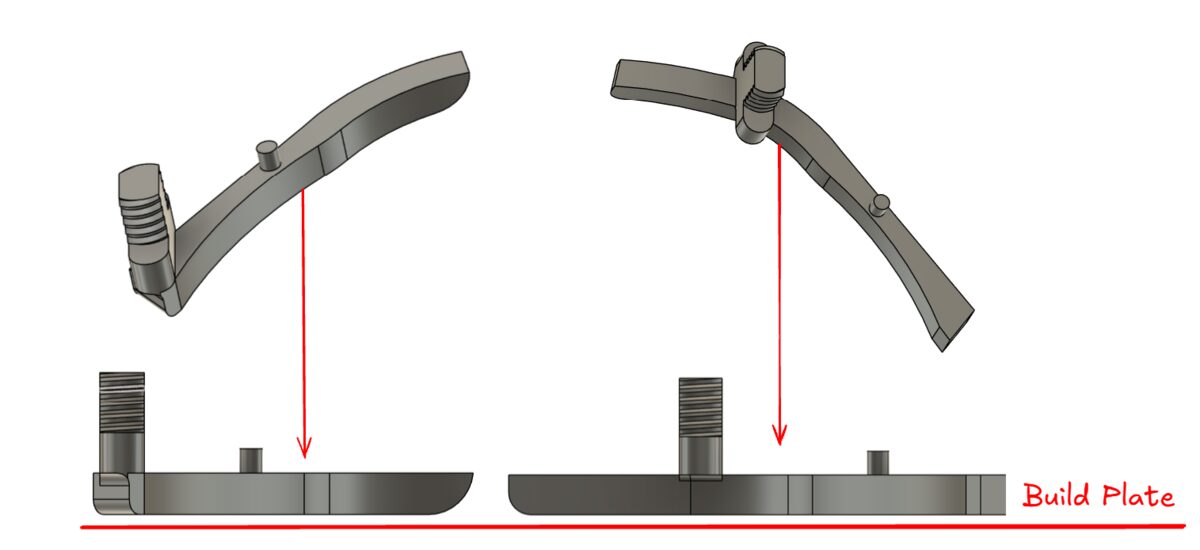
Flappers
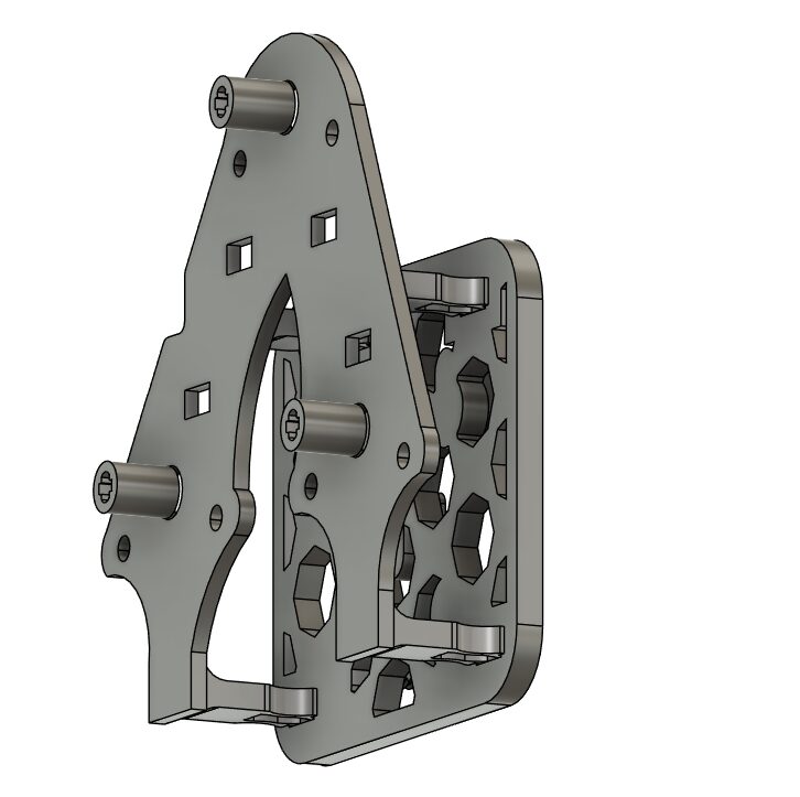
Base – Outer
-
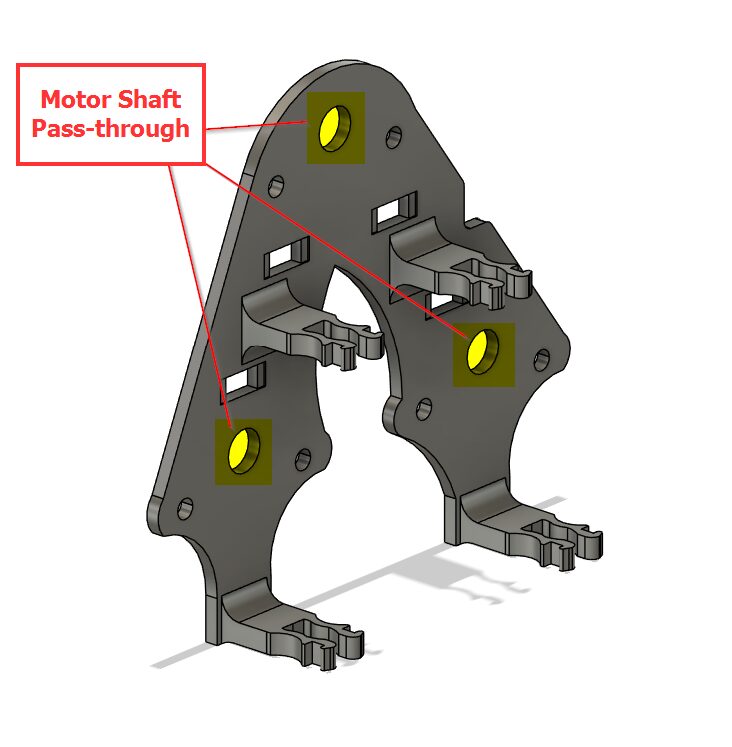
Mount x3 ‘28BYJ-48 stepper motor’ to ‘Base – Leg Left Outer’
-
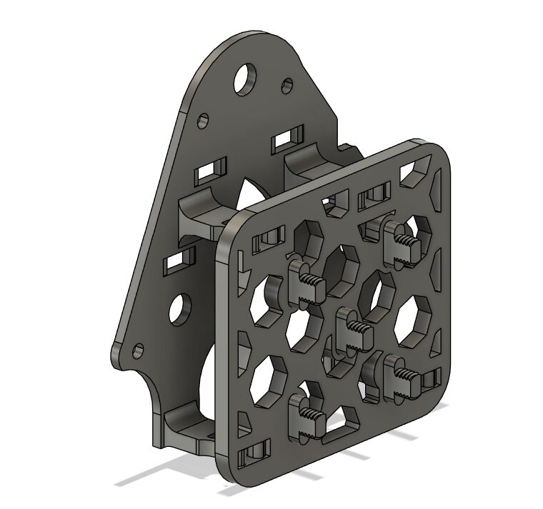
Connect ‘Base – Leg Left Outer’ to ‘Base – Leg Left Mount’
-
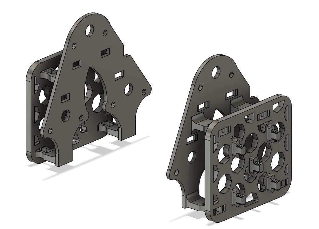
Connect ‘Base – Leg Right Outer’ to ‘Base – Leg Right Mount’
-
Connect 3x ‘Joiner Shaft’ to ‘28BYJ-48 stepper motor’ (heating the motor shafts with a lighter maybe necessary)
Base – Inner
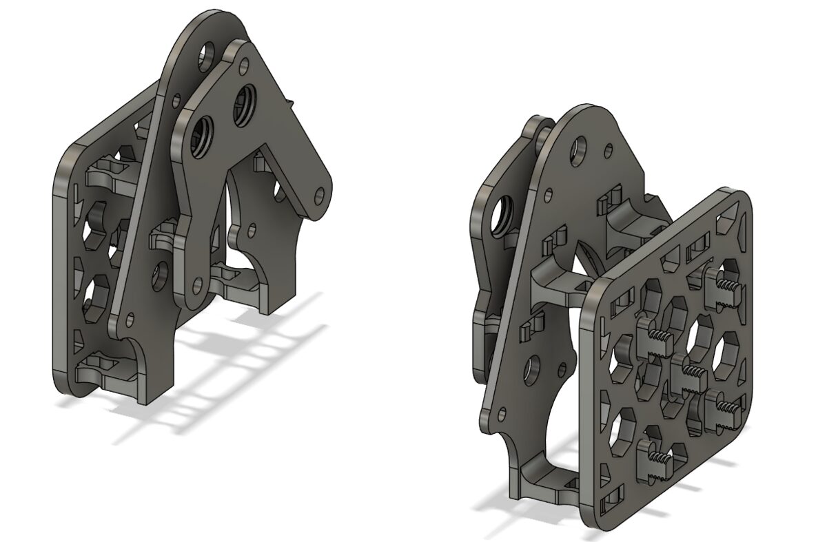
-
Connect ‘Base – Leg Left’ and ‘Base – Leg Right’ to their matching ‘Base – Leg <SIDE> Outer’
-
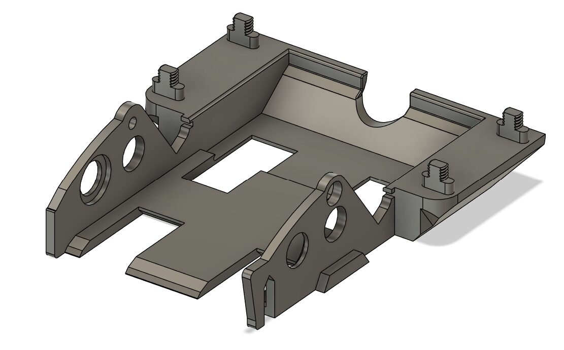
Set previous pieces to the side and grab ‘Base – Center’
-
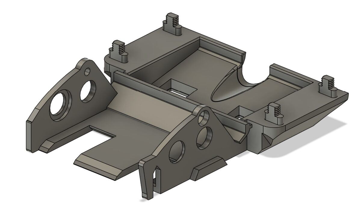
Place ‘Base – Insert’ into ‘Base – Center’
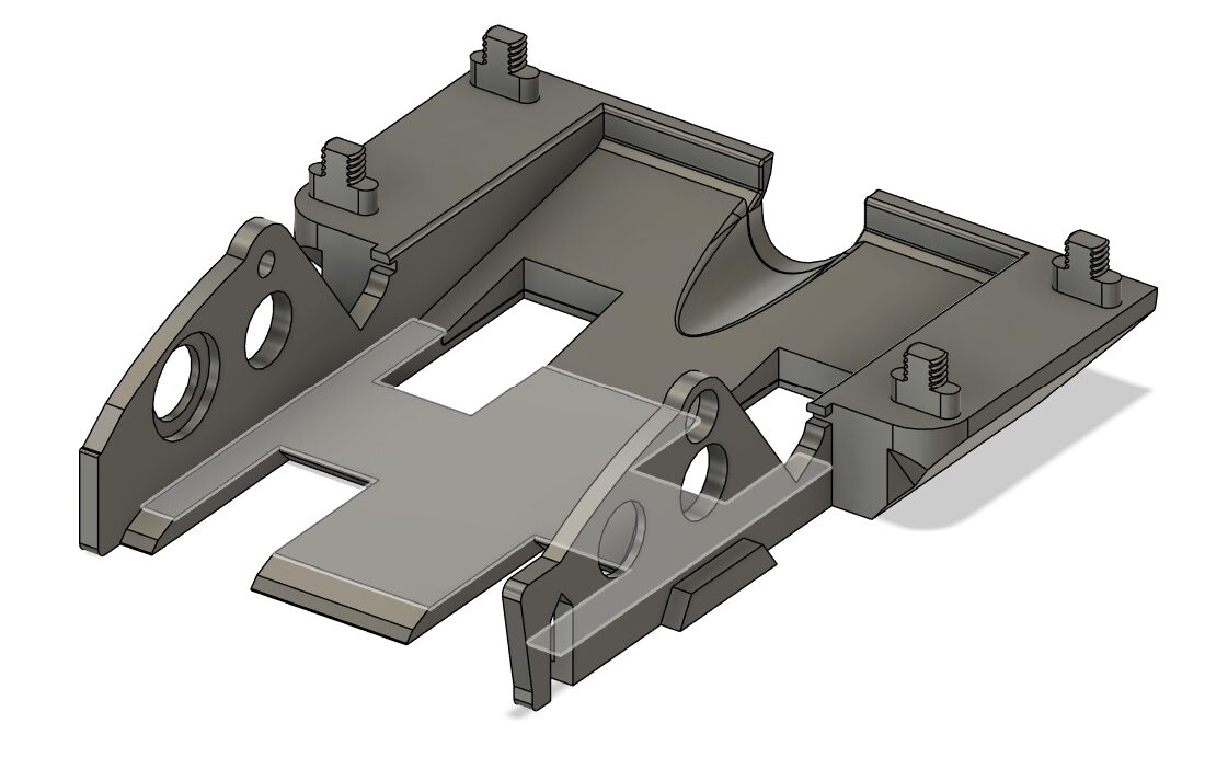
-
Set ‘Base – Guide’ into ‘Base – Center’ making sure the pegs on the left and right set cleanly (sanding if necessary)
-
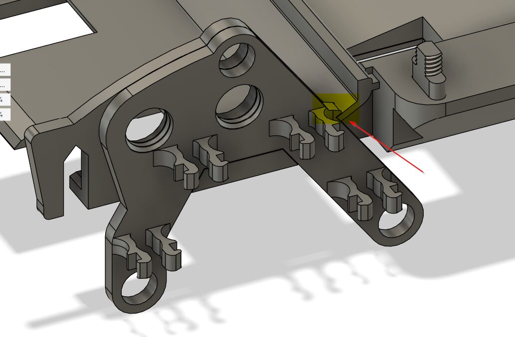
Do not disassemble, view for clarity. Attach parts set aside earlier to the ‘Base – Center’ making sure the retaining peg is on top of ‘Base – Guide’
-
Secure Lego wheels and pegs (not pictured) so two sets of two wheels are on the bottom and two wheels are on the top
-
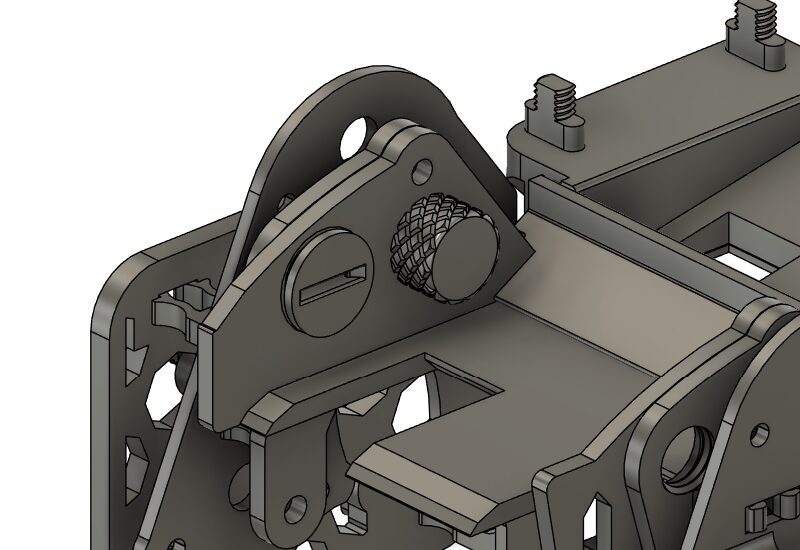
Secure the side together with ‘Screw – Knurled Small’ and ‘Screw – Flat Small’
-
Hopper can be added and removed as wanted; it is omitted from this guide. The Base section is now complete.
Scanner
-
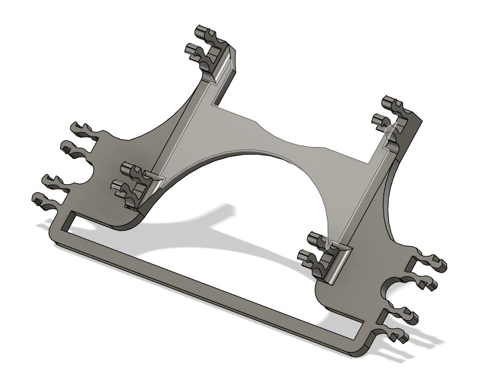
Take ‘Scanner Base Bottom’
-
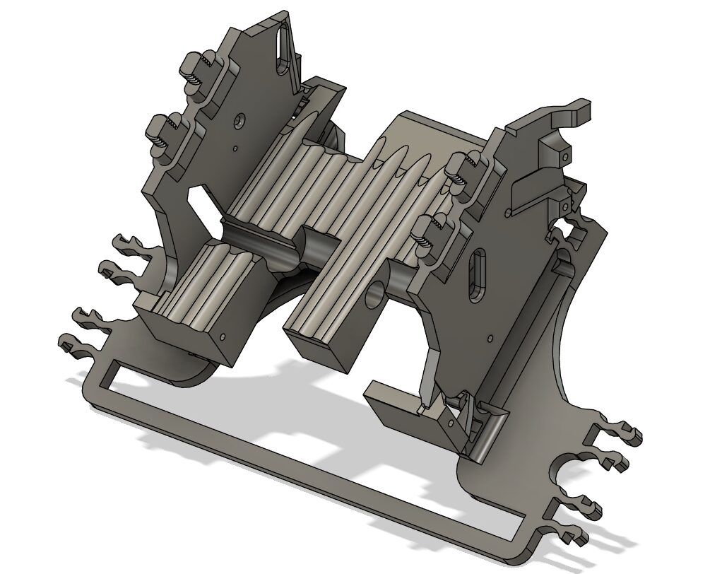
Connect ‘Scanner Base’ to ‘Scanner Base Bottom’
-
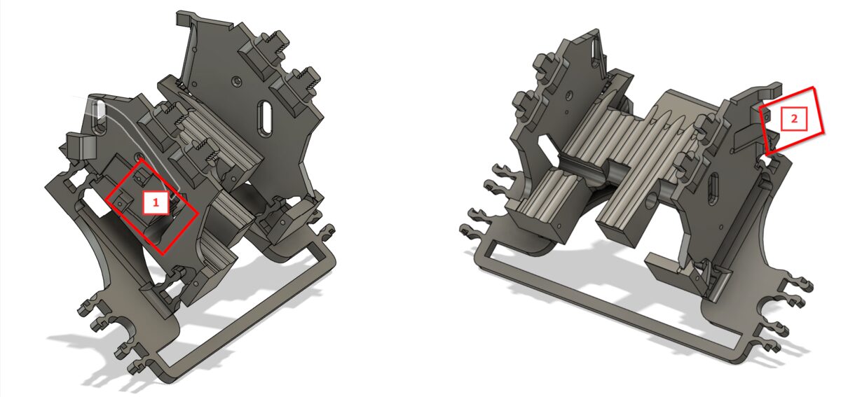
Take two ‘LM393 photoelectric break-beam sensors’ to the ‘Scanner Base’ in spots #1 and #2 — leave the screws for #2 loose for later when connecting to ‘Base – Center’
-
Take an SG90 servo motor, running the cable through hole 1, making sure the motor portion of the servo motor is to the right as shown with #2
-
When connecting the servo motor you will need to connect the arm of the servo so it will be able to rotate between positions #1 & #2 (shown #2 in picture), connecting the ‘Card Kicker’ to the servo arm
-
Take ‘Scanner Outer – Left’ and ‘Scanner Outer – Right’ and connect them to the ‘Scanner Base Bottom’, taking note of the direction of the connectors (red). Then set this piece to the side.
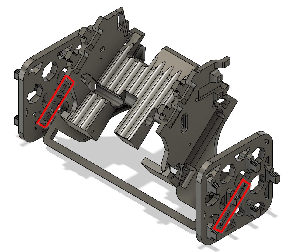
Flappers (Repeat x9)
-
Take ‘Flapper # - Threaded Rod’
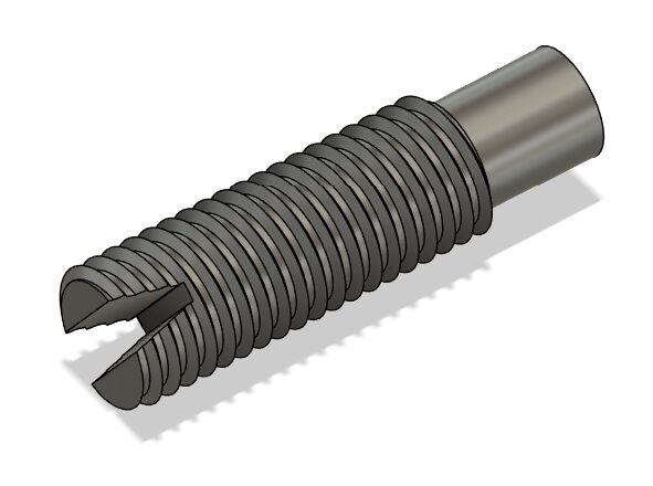
-
Screw it into ‘Flapper # - Mounting Plate’
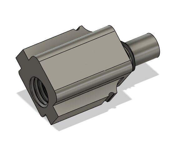
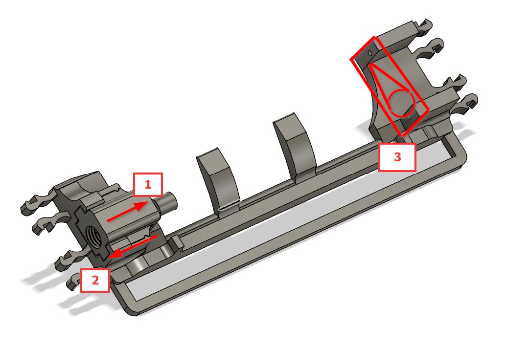
-
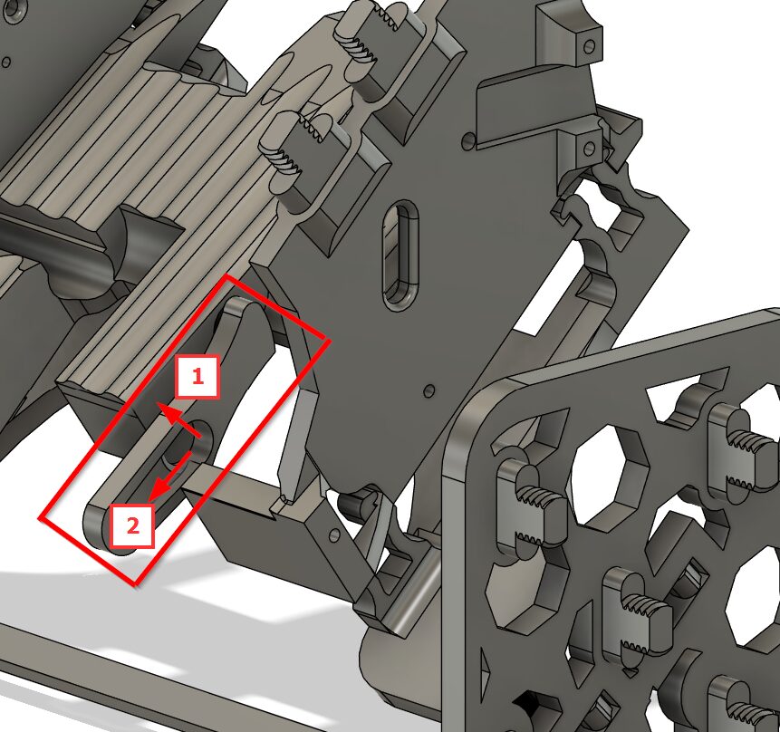
Connect the ‘Flapper # - Mounting Plate’ in the direction of #1 — later, when assembled, it can be pushed in direction #2 to easily remove the Flapper. Screw an SG90 servo motor into position #3 with the white arm attached as shown.
-
Take 3 ‘Flapper Inserts’ (using either the snap fit as shown on the far left, or the normal version — whichever performs best for you)
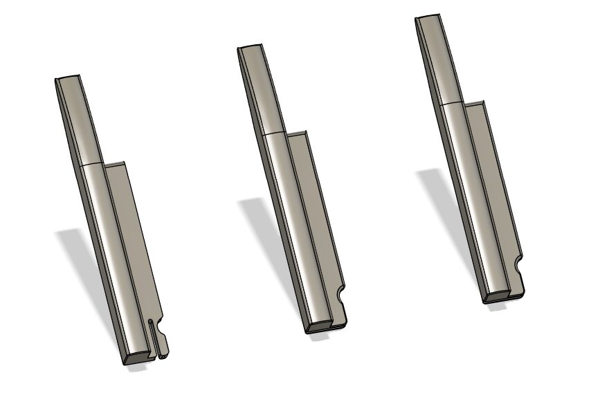
-
Take the ‘Flapper’ and slide the three ‘Flapper Inserts’ in as shown
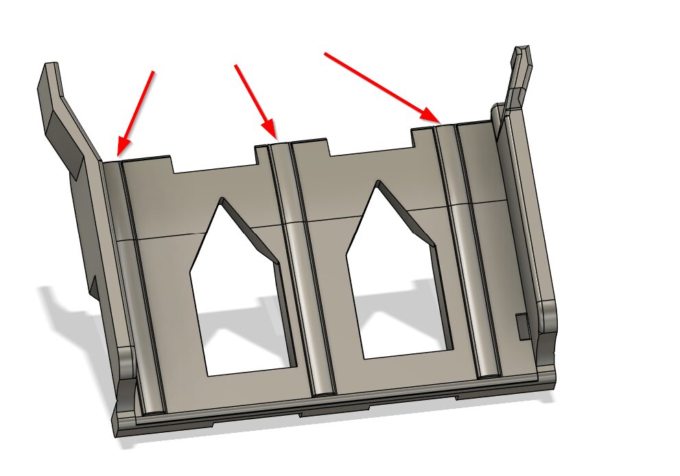
-
Flapper 1 has an additional cut out on the right side due to the proximity of the Raspberry Pi mount plate
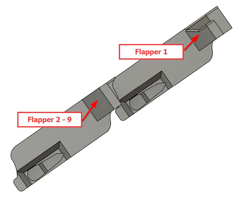
-
Connect the ‘Flapper # - Mount’ to the ‘Flapper # - Left Outer’ and ‘Flapper # - Right Outer’. The outer plates are all labeled with # and L for Left and R for Right.
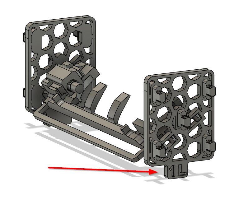
-
The Flapper can be installed once the whole assembly is connected to the Skadis boards, for ease.
Cross Braces (Repeat x2)
-
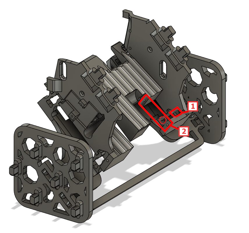
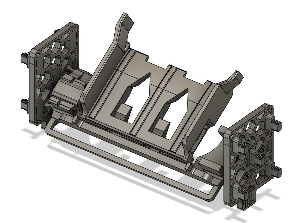
Take ‘Cross Brace – Left’ & ‘Cross Brace – Right’ #1 and connect them together with x2 ‘Cross Brace – Middle’ #2, then set to the side
Raspberry Pi Mount
-
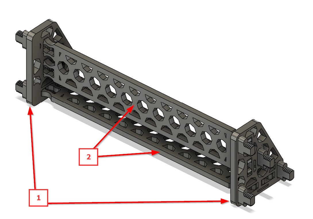
#1 ‘Pi Mount Left’ & ‘Pi Mount Right’ have a long side #2 and a short side #3 — the orientation is important to match as pictured when connecting to ‘Pi Mount’ #4. Set to the side.
Tray
-
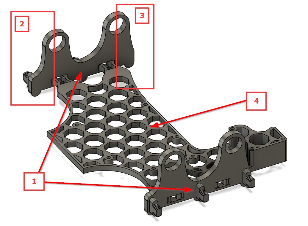
Take the 10 ‘Tray’ items and stack them together
-
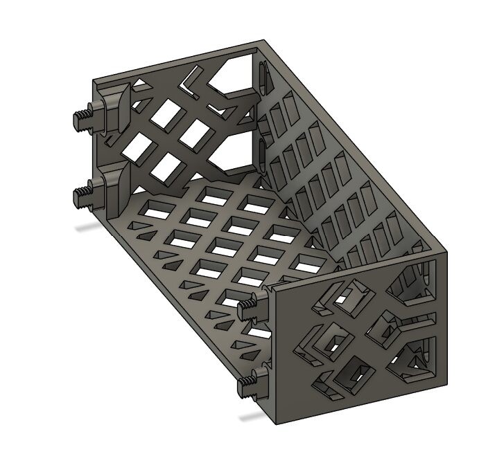
Secure the stacked Trays with 4 nuts ‘Screw – Knurled Large’ #1
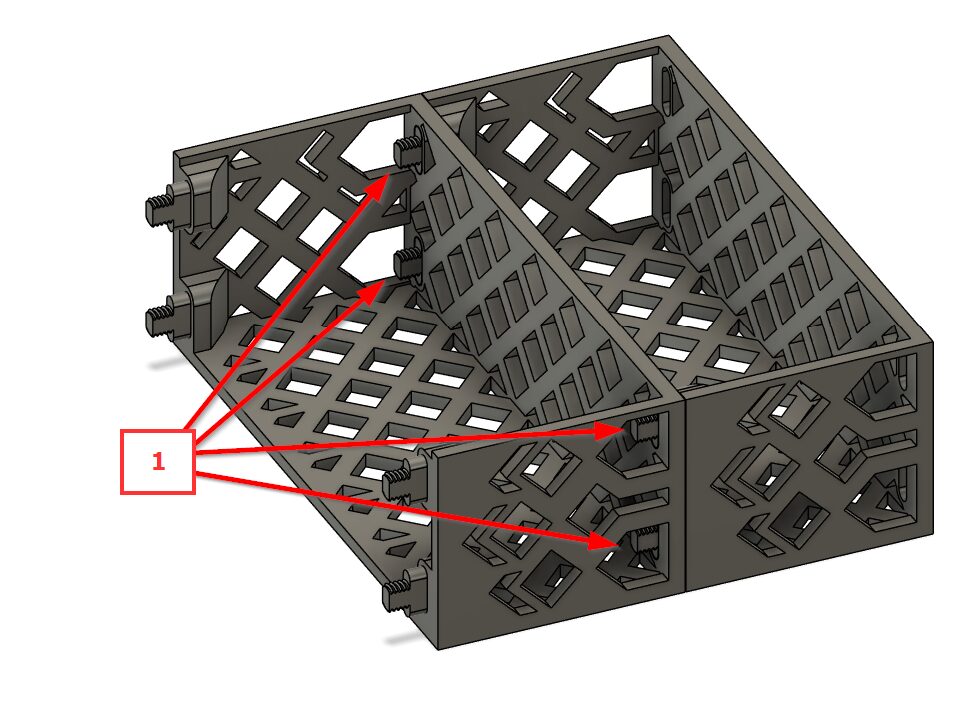
-
Finish the Tray by attaching ‘Tray – Front’, then set to the side
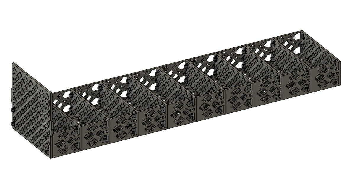
Tray Guides
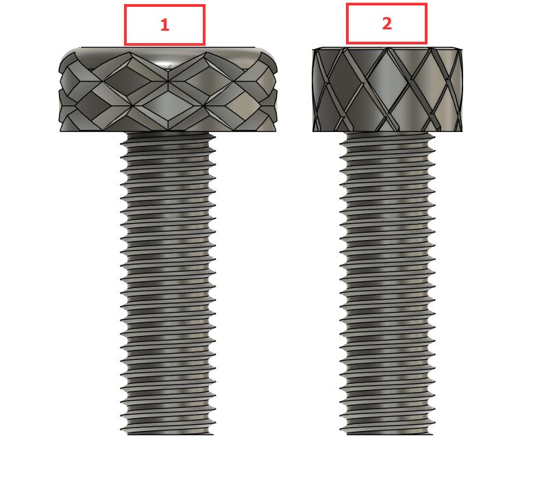
Tray Guide Reference
-
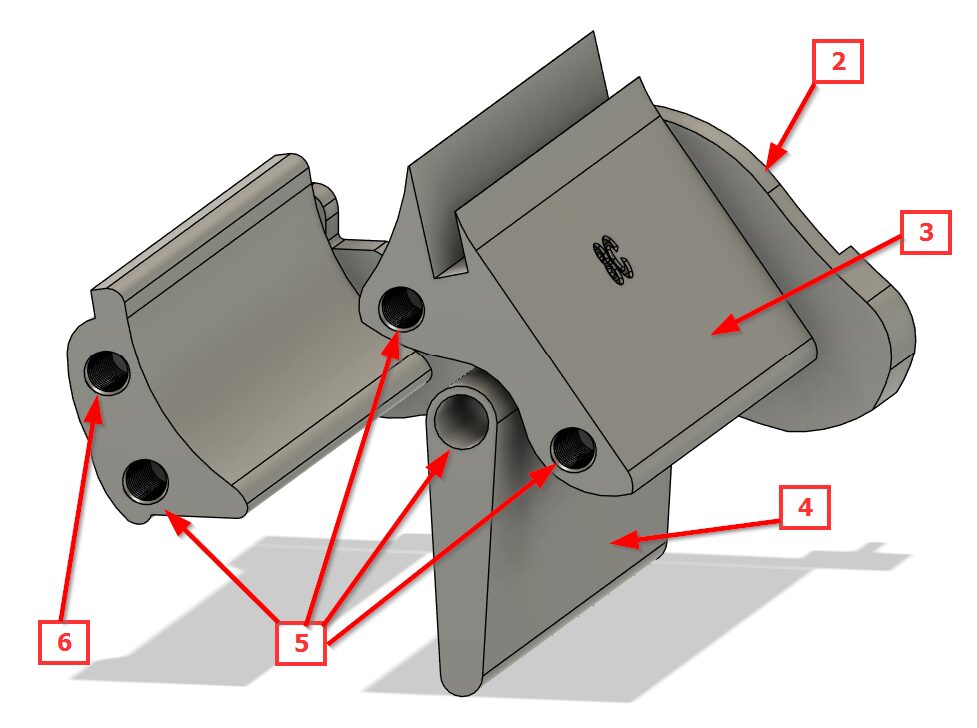
#1 will be used for the tray guides, #2 is only for Guide 8, and there should only be two printed
-
The ‘Center Guide – Flap’ pieces are not labeled, as all 8 are identical
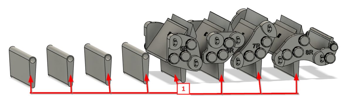
-
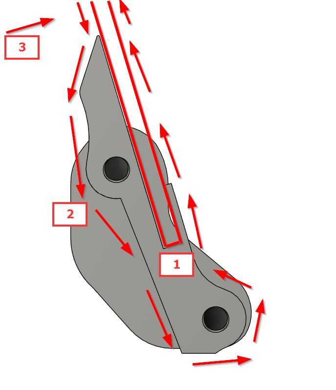
For all tray guides, foam board pieces cut to length will be secured in the guide centers at position #1. To prevent cards from falling between the Center Guide #3 and the foam board, wrap the board in tape (blue painter’s tape works well) in the direction of #2. Wrapping the entire length is recommended, since the tape won’t want to stick to the print — avoid starting the tape where a card could get stuck to it (leave the start and stop at the top of the board).
Guide 0
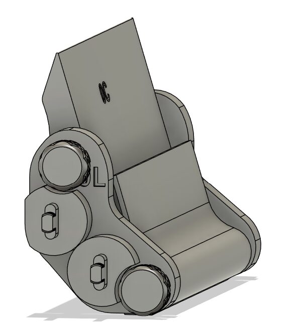
-
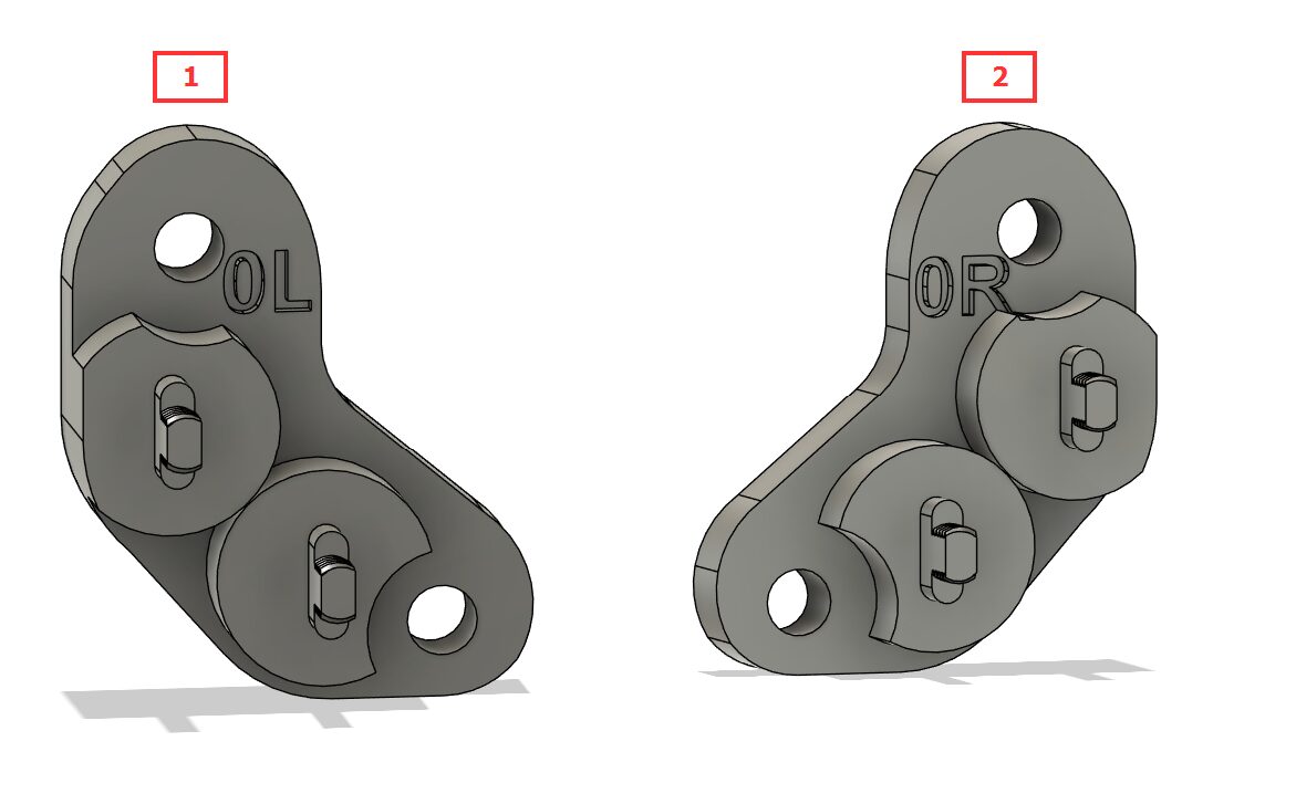
Take #1 ‘Left Guide – 0’ and #2 ‘Right Guide – 0’
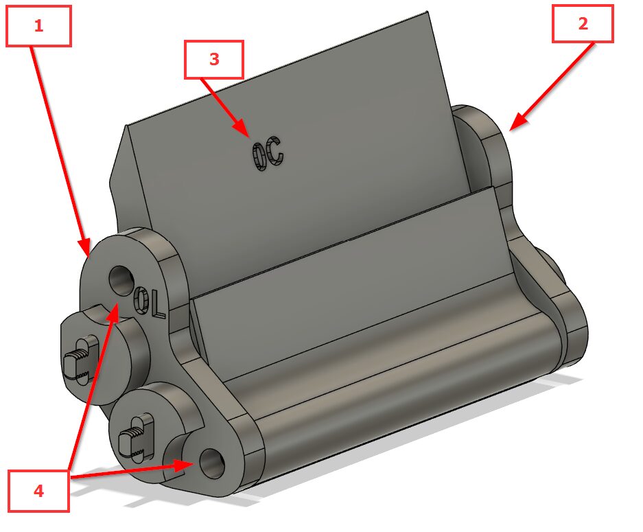
-
Secure pieces 1 & 2 from the previous step to 3 ‘Center Guide – 0’ using screws #1 from step Tray Guide Reference through holes 4 on both sides, then place to the side
Guide 1
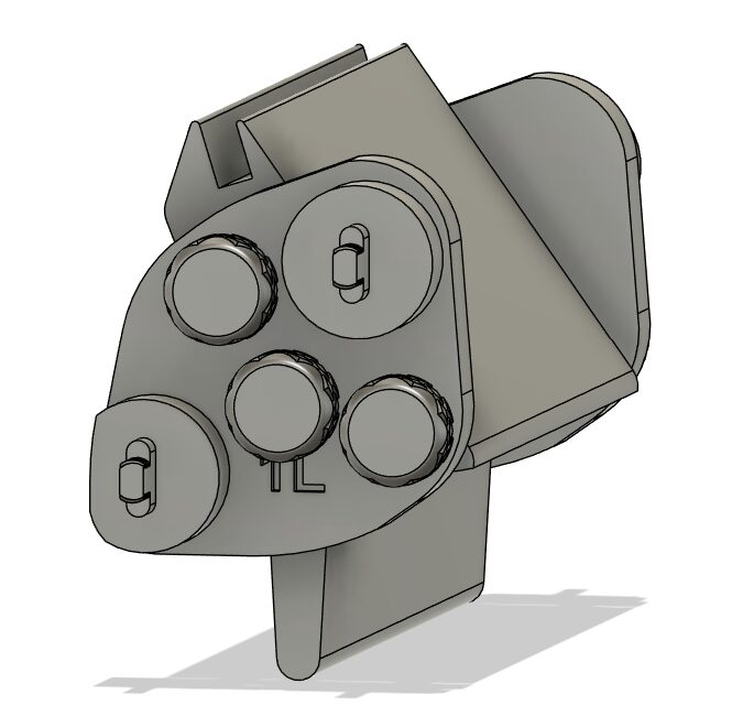
-
Take #1 ‘Left Guide – 1’ and #2 ‘Right Guide – 1’
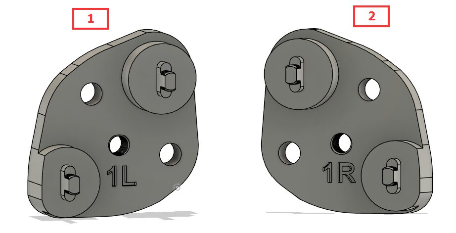
-
Secure pieces 1 (not pictured for clarity) & 2 from the previous step to 3 ‘Center Guide – 1’ and 4 ‘Center Guide – Flap’ using screws #1 from Tray Guide Reference through holes 5 on both sides, then place to the side
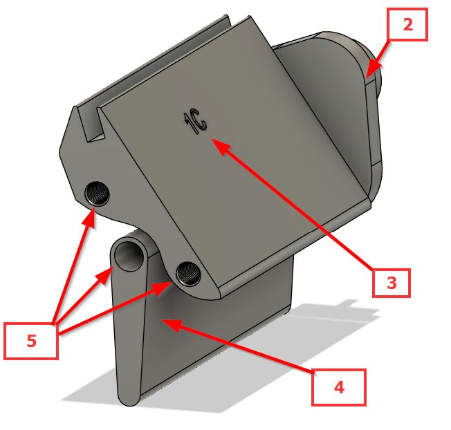
Guide 2

-
Take #1 ‘Left Guide – 2’ and #2 ‘Right Guide – 2’
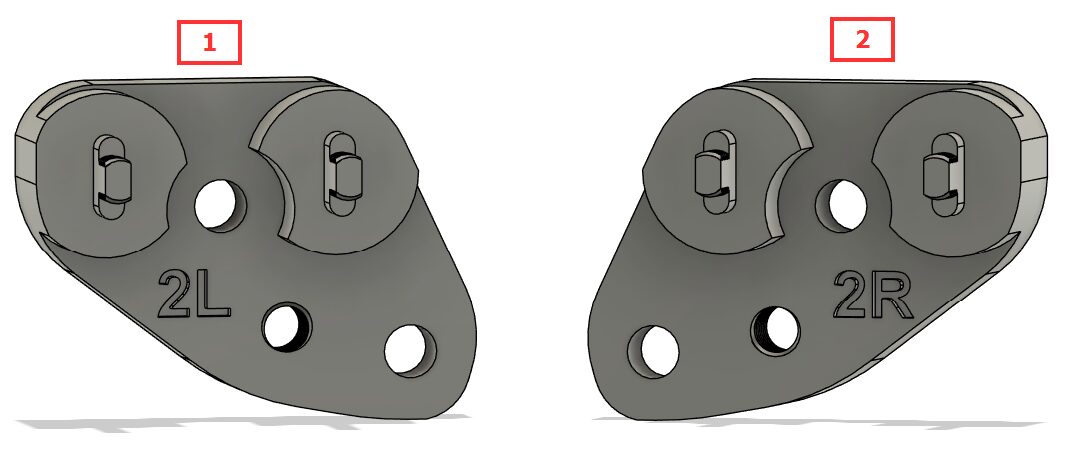
-
Secure pieces 1 (not pictured for clarity) & 2 from the previous step to 3 ‘Center Guide – 2’ and 4 ‘Center Guide – Flap’ using screws #1 from Tray Guide Reference through holes 5 on both sides, then place to the side
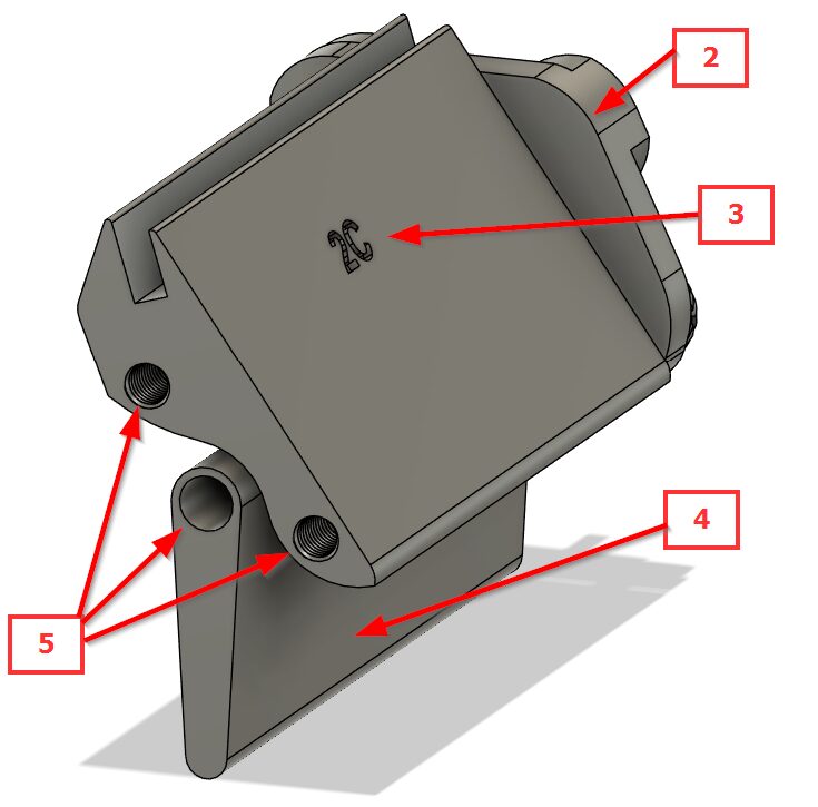
Guide 3
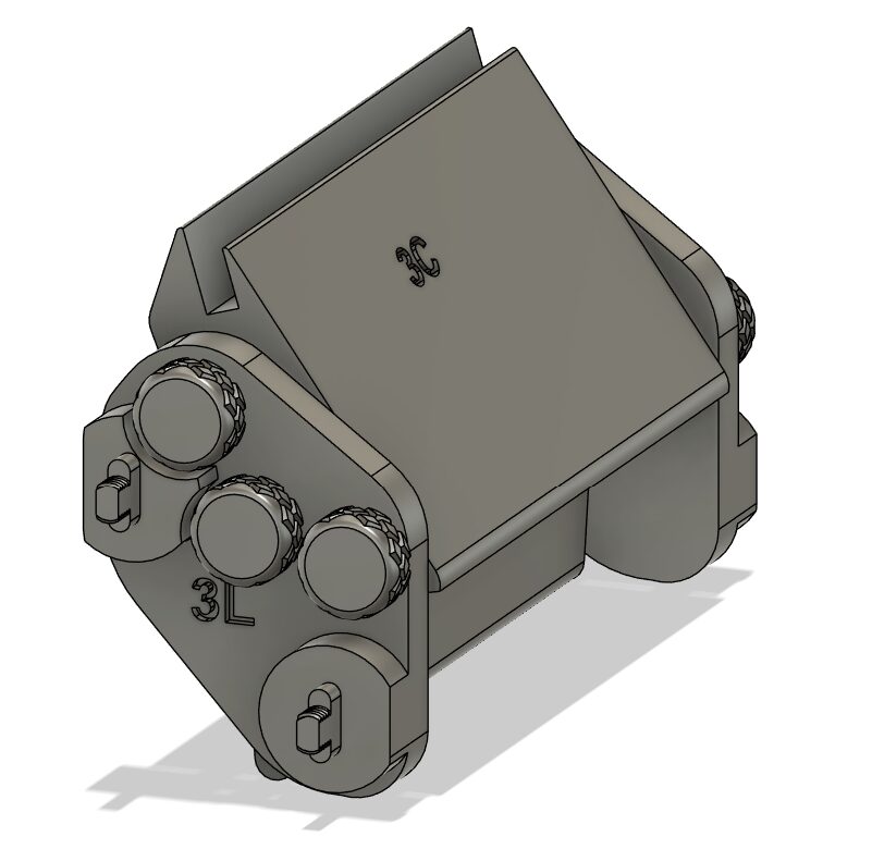
-
Take #1 ‘Left Guide – 3’ and #2 ‘Right Guide – 3’
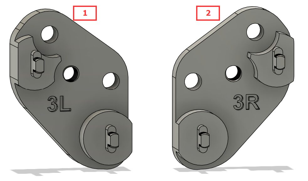
-
Secure pieces 1 (not pictured for clarity) & 2 from the previous step to 3 ‘Center Guide – 3’ and 4 ‘Center Guide – Flap’ using screws #1 from Tray Guide Reference through holes 5 on both sides, then place to the side
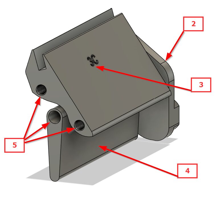
Guide 4
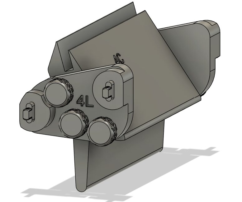
-
Take #1 ‘Left Guide – 4’ and #2 ‘Right Guide – 4’
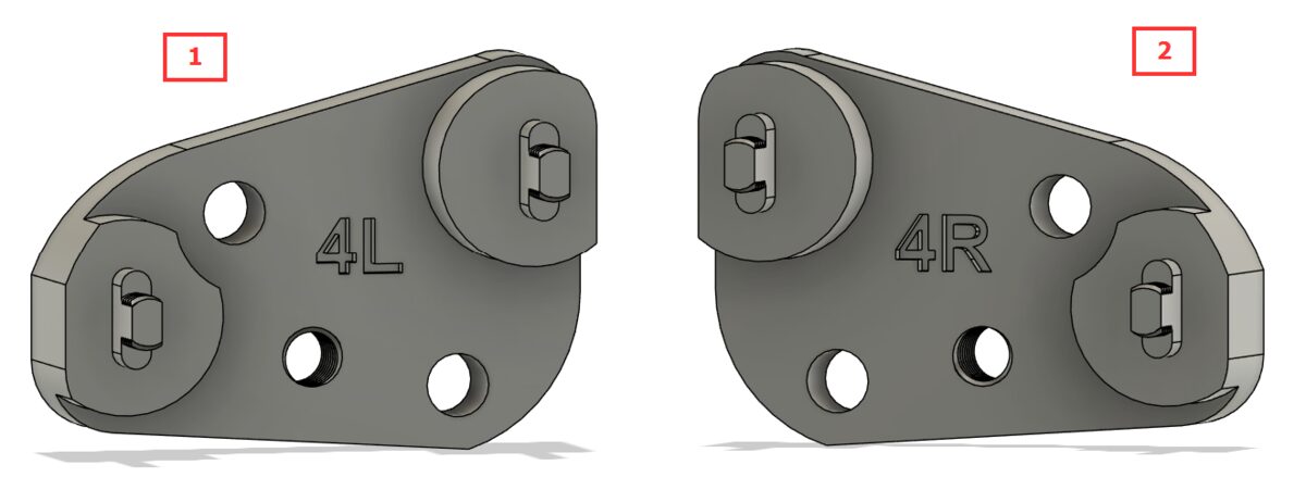
-
Secure pieces 1 (not pictured for clarity) & 2 from the previous step to 3 ‘Center Guide – 4’ and 4 ‘Center Guide – Flap’ using screws #1 from Tray Guide Reference through holes 5 on both sides, then place to the side
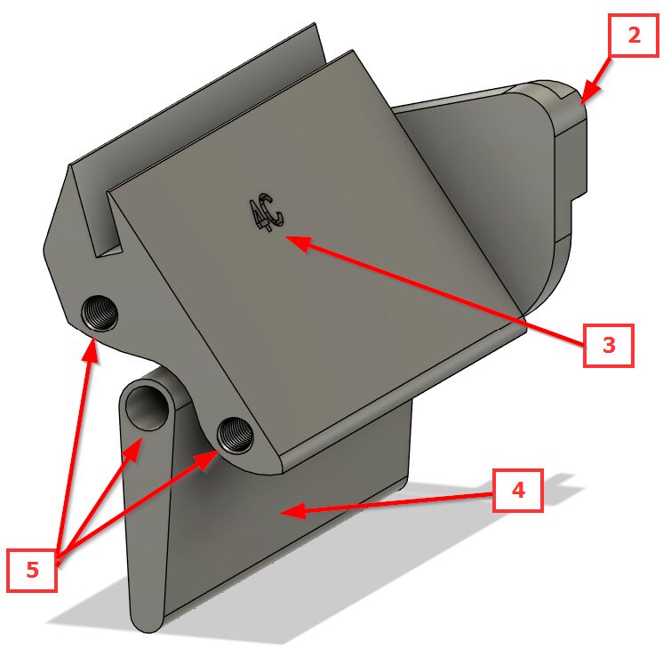
Guide 5
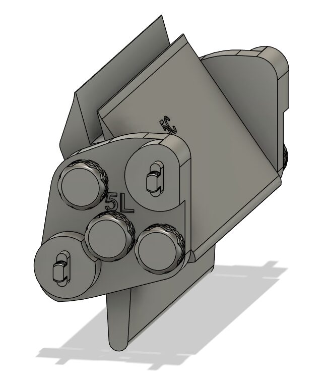
-
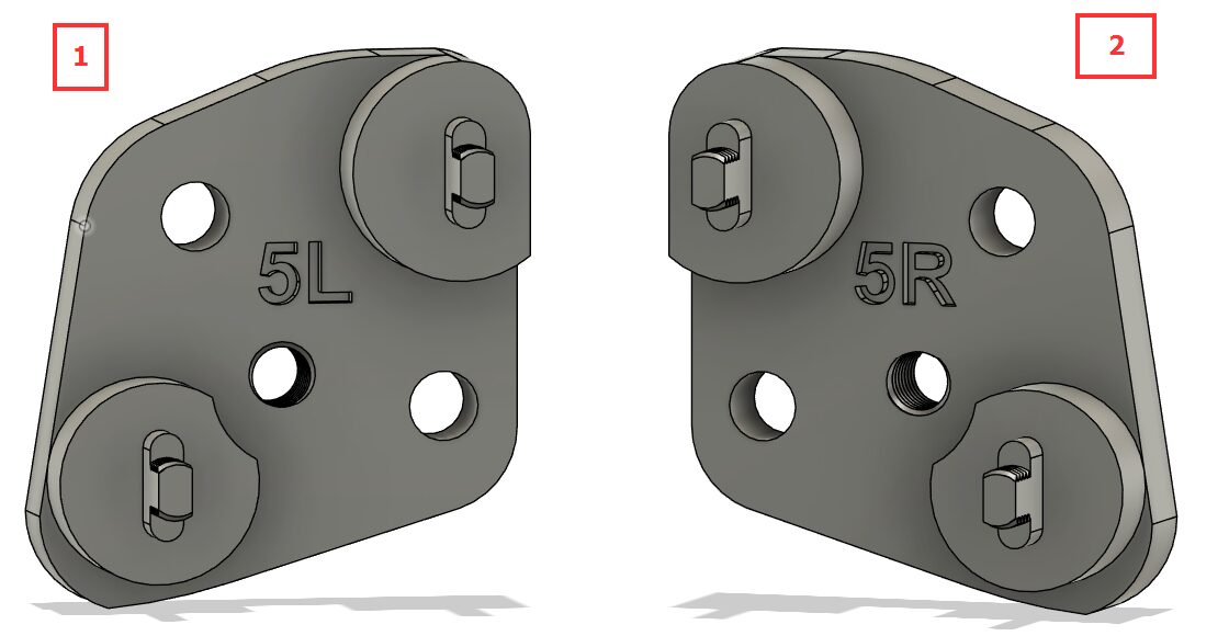
Take #1 ‘Left Guide – 5’ and #2 ‘Right Guide – 5’
-
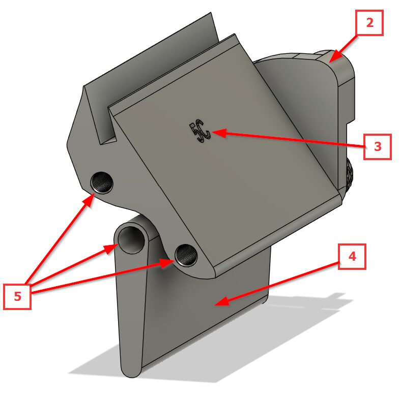
Secure pieces 1 (not pictured for clarity) & 2 from the previous step to 3 ‘Center Guide – 5’ and 4 ‘Center Guide – Flap’ using screws #1 from Tray Guide Reference through holes 5 on both sides, then place to the side
Guide 6
-
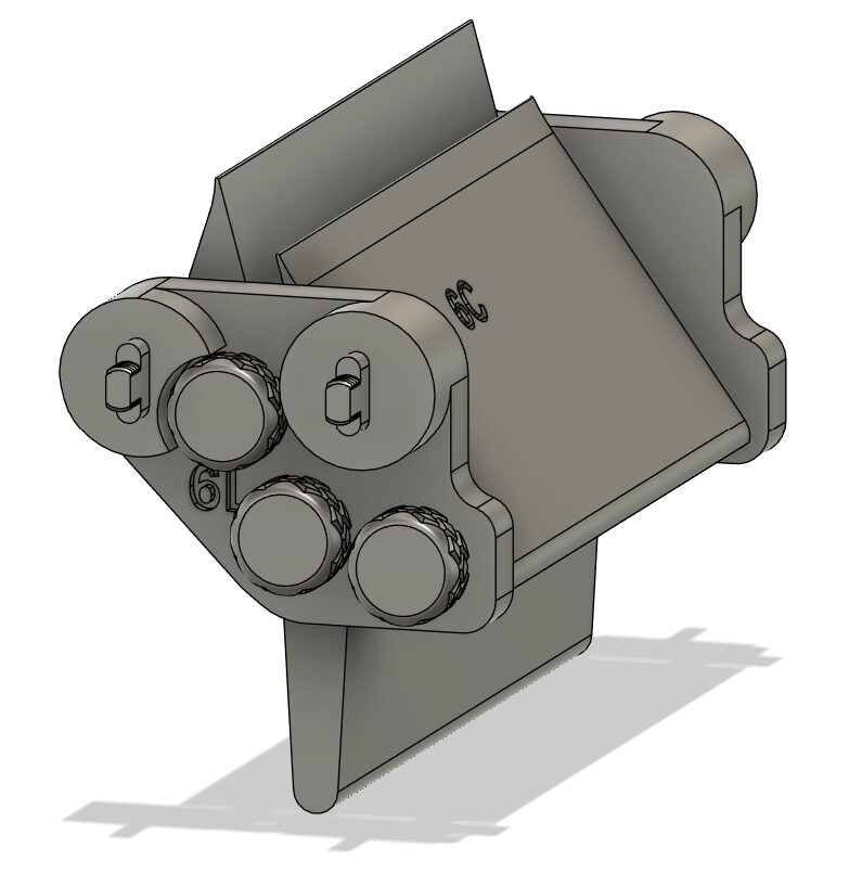
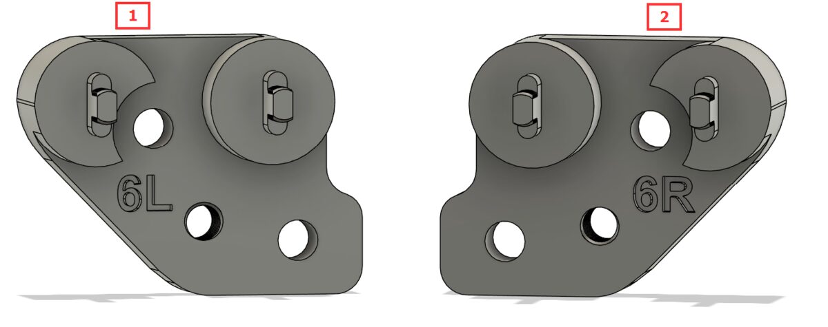
Take #1 ‘Left Guide – 6’ and #2 ‘Right Guide – 6’
-
Secure pieces 1 (not pictured for clarity) & 2 from the previous step to 3 ‘Center Guide – 6’ and 4 ‘Center Guide – Flap’ using screws #1 from Tray Guide Reference through holes 5 on both sides, then place to the side
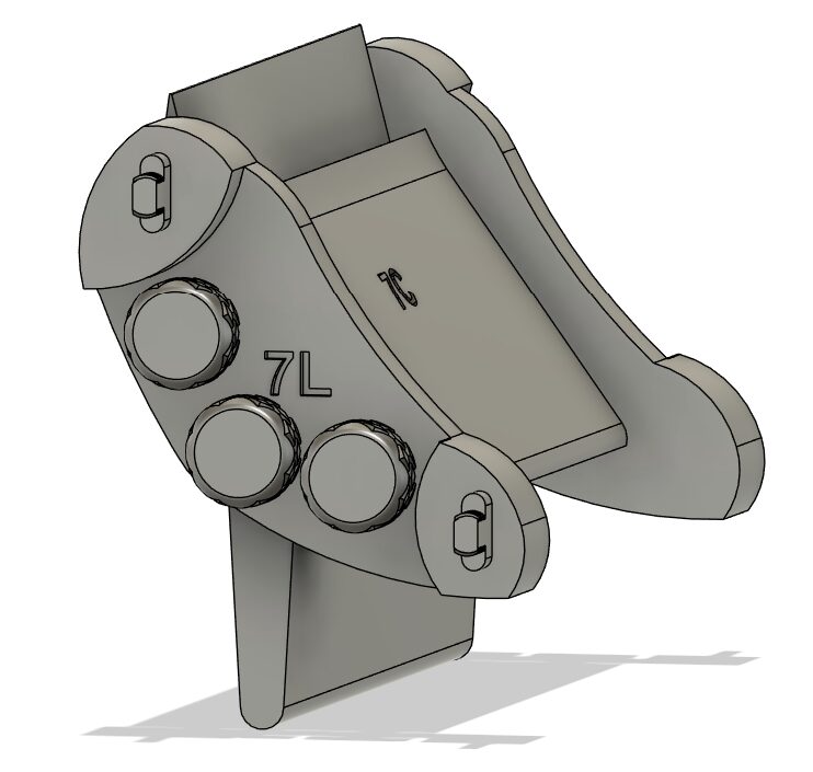
Guide 7
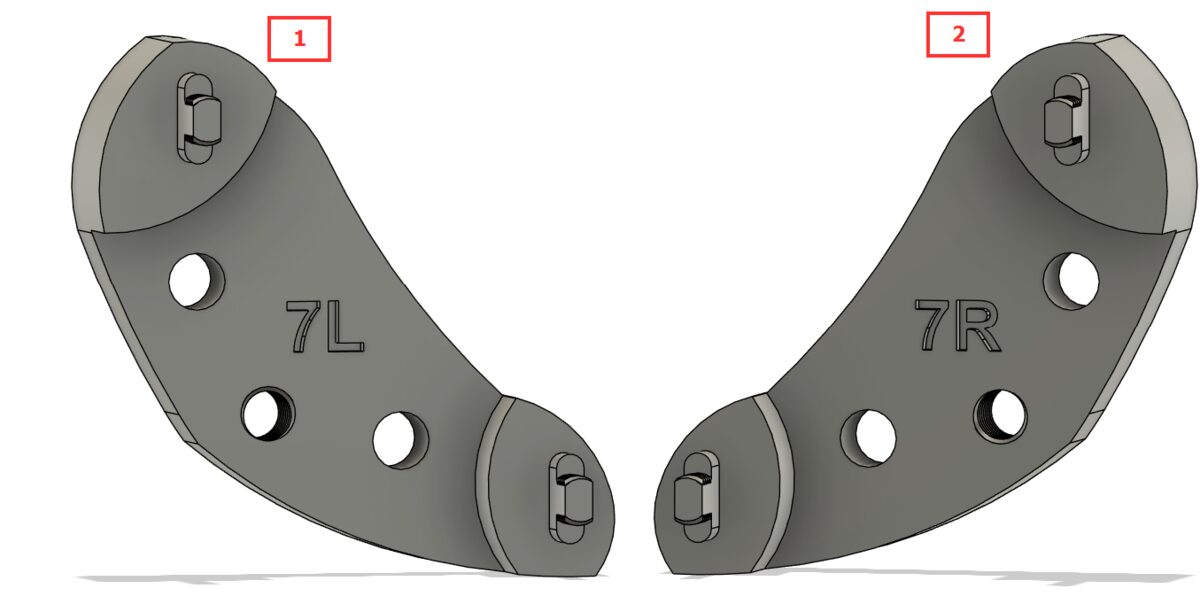
-
Take #1 ‘Left Guide – 7’ and #2 ‘Right Guide – 7’
-
Secure pieces 1 (not pictured for clarity) & 2 from the previous step to 3 ‘Center Guide – 7’ and 4 ‘Center Guide – Flap’ using screws #1 from Tray Guide Reference through holes 5 on both sides, then place to the side
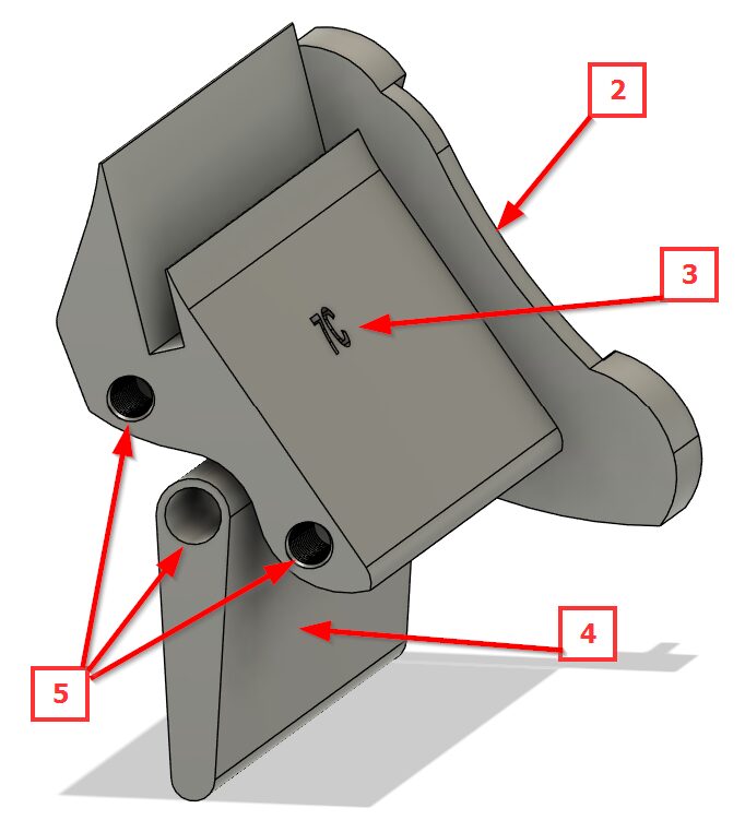
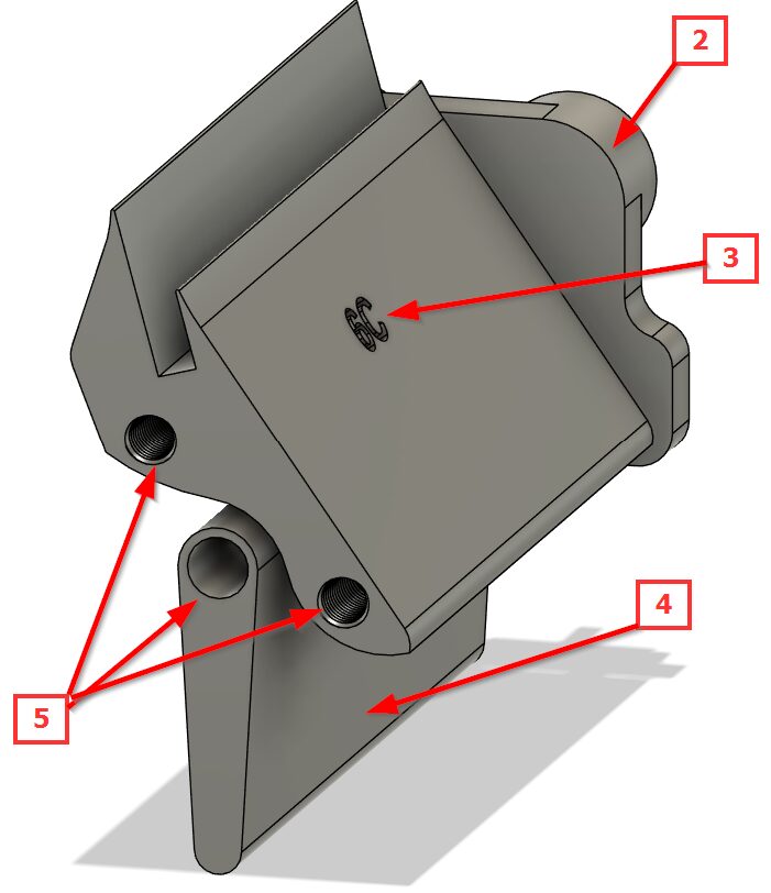
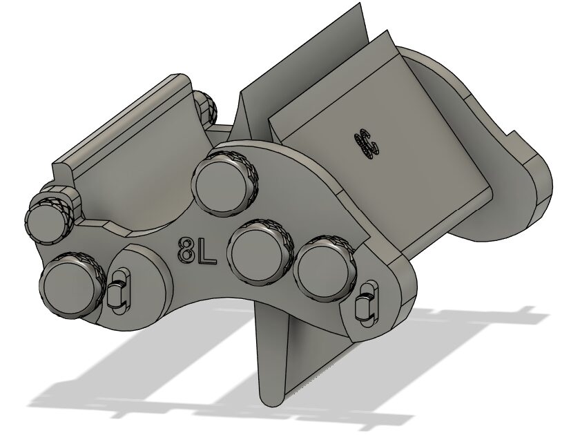
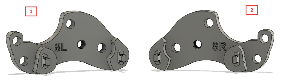
Guide 8
-
Take #1 ‘Left Guide – 8’ and #2 ‘Right Guide – 8’
-
Secure pieces 1 (not pictured for clarity) & 2 from the previous step to 3 ‘Center Guide – 8’ and 4 ‘Center Guide – Flap’ using screws #1 from Tray Guide Reference through holes 5 on both sides, then use screw #2 from the same step through hole 6 on both sides, then place to the side
Final Assembly
Connecting to Skadis Boards
-
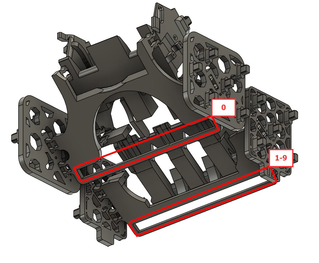
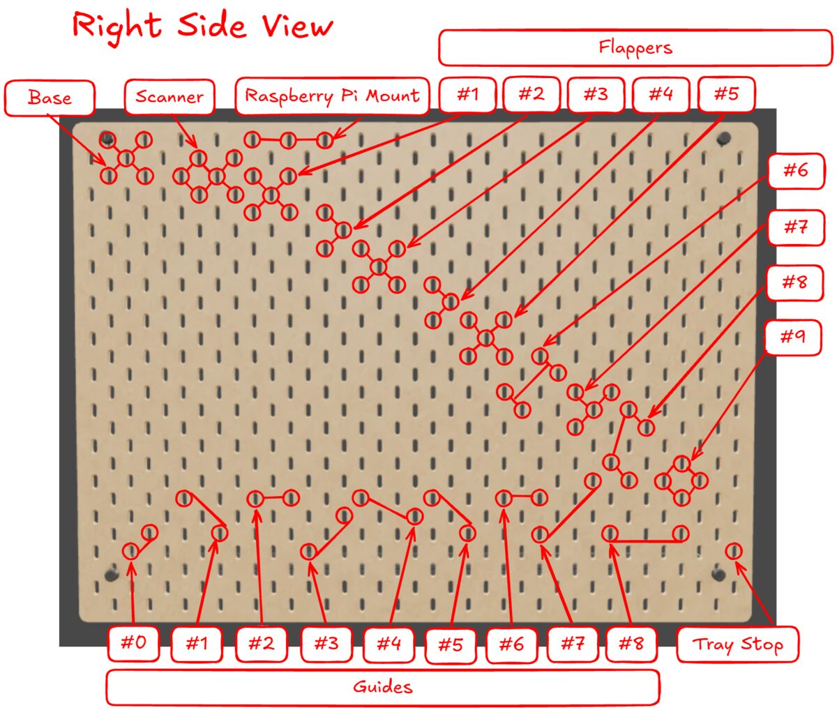
This assumes you have taped all of the foam board cut outs to the bottom guide pieces. Foam board from Guide 0 goes into the Scanner Base, and foam board from Guides 1–8 go into Flapper bases 1–8, with Flapper Base 9 having its piece printed on Guide 8.
-
It’s recommended to leave the Flappers removed from the servos so you are only trying to mount the bases.
-
For final assembly, secure all the pieces to one side of the board as shown in the picture, then flip the assembly over and adjust the pegs into the correct holes so the board drops into place. It’s easiest to work from the top-left corner to the bottom-right, checking the bottom as you go — it should not take force.
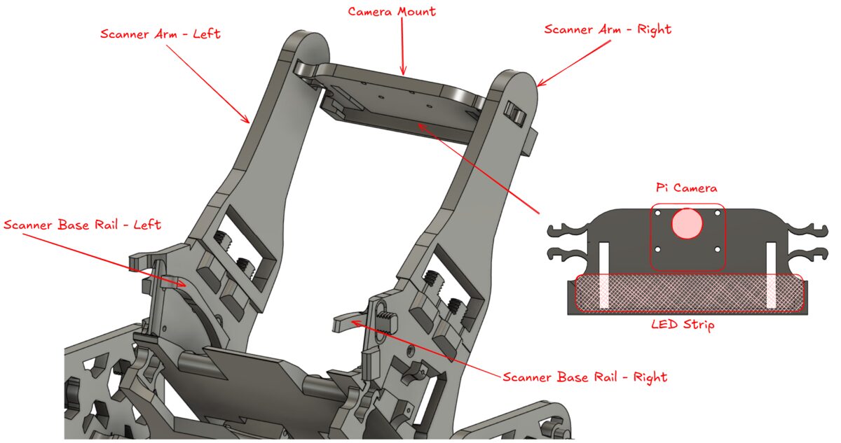
Scanner Rails & Camera Mount
-
Secure the ‘Scanner Base Rail – Left’ and ‘Scanner Base Rail – Right’ to the Scanner
-
Secure the Pi Camera and LED strip to the ‘Camera Mount’, then attach it to the ‘Scanner Arm – Left & Right’ (having the open areas on the bottom of the arms facing outwards)
Wiring
-
Raspberry Pi and Servo HAT shown in proper orientation to the ‘Raspberry Pi Mount’
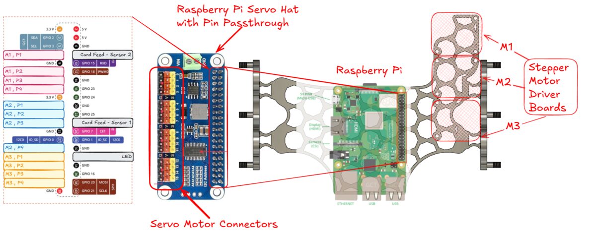
-
Servo Motor Connectors — Pins 0 to Scanner Servo, Pins 1 through 9 to Flapper servos 1 through 9
Extras
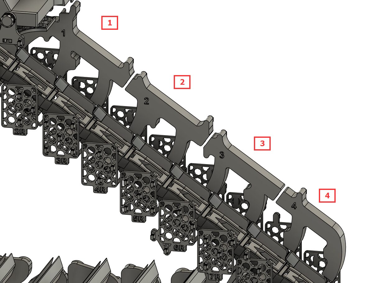
Cable Guides
There are 4 Cable Guides that can be printed to help maintain the clean appearance of the servo wires — this would be the last step in the assembly.
Feet
Feet can be facing inwards (good for placing on carpet) or outwards (tip-over prevention). You will need to print at least 6 (though 10 recommended) for placing evenly along the bottom edge of the Skadis boards.
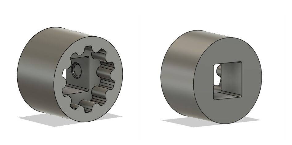
Quarter-Inch Drive Adapter
Available to print is an adapter to help turn the Knurled Nuts that fits on a standard ¼” drive.
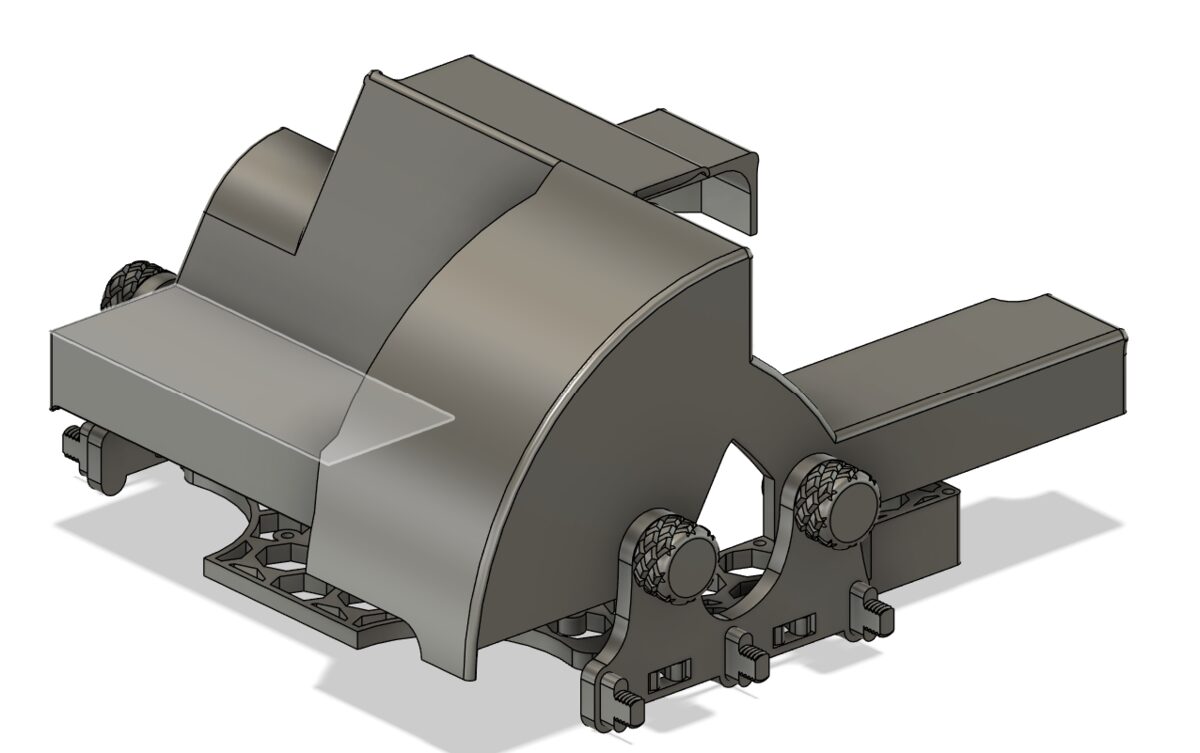
Shroud
The Shroud to cover the Raspberry Pi and cables is secured by 4x #1 screws (from the Tray Guide Reference step) to the Raspberry Pi mount.
Hopper
Hopper #1 mounted on top of the Base, and secured with x4 large nuts, provides extra capacity and additional tension on the top axle.